“SKU:RB-02S043 光电测速码盘套件”的版本间的差异
来自ALSROBOT WiKi
(以“右 ==产品概述== Arduino 光电码盘是哈尔滨奥松机器人科技有限公司2012年最新推出的光电测试传感...”为内容创建页面) |
(→使用方法) |
||
| 第15行: | 第15行: | ||
* -:地(GND) | * -:地(GND) | ||
==使用方法== | ==使用方法== | ||
| − | === | + | ===接线方法1=== |
将光电测速码盘的 S 端口接到控制器的数字 I/O 口 5,+ 和-分别接到电源的 +5V 和 GND。 | 将光电测速码盘的 S 端口接到控制器的数字 I/O 口 5,+ 和-分别接到电源的 +5V 和 GND。 | ||
| − | === | + | ===例子程序1=== |
<pre style='color:blue'> | <pre style='color:blue'> | ||
#include "MsTimer2.h" | #include "MsTimer2.h" | ||
| 第56行: | 第56行: | ||
Serial.println(" RPM"); | Serial.println(" RPM"); | ||
}</pre> | }</pre> | ||
| − | === | + | ===程序效果1=== |
在串口打印出"rotate speed ="及 "RPM"相关数据 | 在串口打印出"rotate speed ="及 "RPM"相关数据 | ||
| + | |||
| + | ===接线方法2=== | ||
| + | 将光电测速码盘1的 S 端口接到控制器的数字 I/O 口 2,+ 和-分别接到电源的 +5V 和 GND<br/> | ||
| + | 将光电测速码盘2的 S 端口接到控制器的数字 I/O 口 3,+ 和-分别接到电源的 +5V 和 GND<br/> | ||
| + | ===例子程序2=== | ||
| + | <pre style='color:blue'>#include "TimerOne.h" | ||
| + | |||
| + | const byte MOTOR1 = 2; // Motor 1 使用外部中断 0 | ||
| + | const byte MOTOR2 = 3; // Motor 2 使用外部中断 1 | ||
| + | |||
| + | unsigned int counter1 = 0; | ||
| + | unsigned int counter2 = 0; | ||
| + | |||
| + | float diskslots = 10; //码盘数 | ||
| + | |||
| + | void ISR_count1() | ||
| + | { | ||
| + | counter1++; //Motor1 | ||
| + | } | ||
| + | |||
| + | void ISR_count2() | ||
| + | { | ||
| + | counter2++; //Motor 2 | ||
| + | } | ||
| + | |||
| + | // TimerOne 中断 | ||
| + | void ISR_timerone() | ||
| + | { | ||
| + | Timer1.detachInterrupt(); // Stop the timer | ||
| + | Serial.print("Motor Speed 1: "); | ||
| + | float rotation1 = (counter1 / diskslots) * 60.00; // Motor 1 | ||
| + | Serial.print(rotation1); | ||
| + | Serial.print(" RPM "); | ||
| + | counter1 = 0; | ||
| + | Serial.print("Motor Speed 2: "); | ||
| + | float rotation2 = (counter2 / diskslots) * 60.00; // Motor 2 | ||
| + | Serial.print(rotation2); | ||
| + | Serial.println(" RPM"); | ||
| + | counter2 = 0; | ||
| + | Timer1.attachInterrupt( ISR_timerone ); | ||
| + | } | ||
| + | |||
| + | void setup() | ||
| + | { | ||
| + | Serial.begin(9600); | ||
| + | |||
| + | Timer1.initialize(1000000); // 设定时间为 1s | ||
| + | attachInterrupt(digitalPinToInterrupt (MOTOR1), ISR_count1, RISING); // 当检测到上升沿时,计数 | ||
| + | attachInterrupt(digitalPinToInterrupt (MOTOR2), ISR_count2, RISING); | ||
| + | Timer1.attachInterrupt( ISR_timerone ); // 开启Timer中断 | ||
| + | } | ||
| + | |||
| + | void loop() | ||
| + | { | ||
| + | |||
| + | }</pre> | ||
| + | |||
| + | ===程序效果2=== | ||
| + | 通过串口打印出两个电机的转速 | ||
| + | |||
==产品相关推荐== | ==产品相关推荐== | ||
[[文件:erweima.png|230px|无框|右]] | [[文件:erweima.png|230px|无框|右]] | ||
2018年6月1日 (五) 15:13的版本
目录 |
产品概述
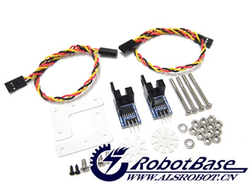
Arduino 光电码盘是哈尔滨奥松机器人科技有限公司2012年最新推出的光电测试传感器,该产品是一款短响应速度、开关量输出的测速模组,配合白色码盘可以测量电机转速,该款测试码盘可以直接固定到双输出轴直流减速电机上方便安装,简单易用。
规格参数
- 工作电压:5v DC
- 工作电流:小于 20mA
- 工作温度:10℃ - 30℃
- 与传感器扩展板I/O兼容
- 传感器类型:模拟输出
- 平面尺寸:15×35×16mm
- 重量大小:24g
接口定义
- S:信号控制端(Signal)
- +:电源(VCC)
- -:地(GND)
使用方法
接线方法1
将光电测速码盘的 S 端口接到控制器的数字 I/O 口 5,+ 和-分别接到电源的 +5V 和 GND。
例子程序1
#include "MsTimer2.h"
#define ENCODER_READ 5
unsigned int encoderPos,a;
void setup()
{
    Serial.begin(9600);
    MsTimer2::set(1000, flash); // 500ms period
    MsTimer2::start();
    counterStart();
}

void loop()
{
}
void counterStart()
{
  TCCR1A=0;
  TCCR1B=0;
  TCNT1=0;
  TCCR1B = TCCR1B | 7;
}
unsigned int getCount()
{
  unsigned int count;
  count = TCNT1;
  TCNT1=0;
  TCCR1B = TCCR1B & ~7;
  TCCR1B = TCCR1B | 7;
  return count;
}
void flash() {
encoderPos = getCount();
a=encoderPos*6;
Serial.print("rotate speed = ");
Serial.print(a);
Serial.println(" RPM");
}
程序效果1
在串口打印出"rotate speed ="及 "RPM"相关数据
接线方法2
将光电测速码盘1的 S 端口接到控制器的数字 I/O 口 2,+ 和-分别接到电源的 +5V 和 GND
将光电测速码盘2的 S 端口接到控制器的数字 I/O 口 3,+ 和-分别接到电源的 +5V 和 GND
例子程序2
#include "TimerOne.h"

const byte MOTOR1 = 2;  // Motor 1 使用外部中断 0
const byte MOTOR2 = 3;  // Motor 2 使用外部中断 1

unsigned int counter1 = 0;
unsigned int counter2 = 0;

float diskslots = 10;  //码盘数

void ISR_count1()
{
  counter1++;  //Motor1
}

void ISR_count2()
{
  counter2++;  //Motor 2
}

// TimerOne 中断
void ISR_timerone()
{
  Timer1.detachInterrupt();  // Stop the timer
  Serial.print("Motor Speed 1: ");
  float rotation1 = (counter1 / diskslots) * 60.00;  // Motor 1
  Serial.print(rotation1);
  Serial.print(" RPM  ");
  counter1 = 0;
  Serial.print("Motor Speed 2: ");
  float rotation2 = (counter2 / diskslots) * 60.00;  // Motor 2
  Serial.print(rotation2);
  Serial.println(" RPM");
  counter2 = 0;
  Timer1.attachInterrupt( ISR_timerone );
}

void setup()
{
  Serial.begin(9600);

  Timer1.initialize(1000000); // 设定时间为 1s
  attachInterrupt(digitalPinToInterrupt (MOTOR1), ISR_count1, RISING);  // 当检测到上升沿时,计数
  attachInterrupt(digitalPinToInterrupt (MOTOR2), ISR_count2, RISING);
  Timer1.attachInterrupt( ISR_timerone ); // 开启Timer中断
}

void loop()
{

}
程序效果2
通过串口打印出两个电机的转速
产品相关推荐
购买地址
周边产品推荐
Arduino 4WD铝合金移动平台车灯套件
Arduino 光电码盘 光电测速传感器

